The ESP32 has a powerful dual processor, Bluetooth, two hardware serial ports, and 34 GPIO pins making it a very popular gateway hub device for the Internet Of Things (IoT). In his tutorial we will how you how to connect the JemRF Flex module to the ESP32 Development Board so you can interface all the JemRF sensors with PrivateEyePi.
What you will need
- ESP32 Development board. There are many variants available but make sure GPIO pins 16 (TX2) and 17 (RX2) (Serial Port 2) are exposed. The ESP32 has two hardware serial ports and we will be using Serial Port 2 to connect the Flex RF module, so that you can use Serial Port 1 for debugging.
- FlexRF Module.
- Breadboard(optional if you want to interface JemRF sensors) for easy installation. Both the ESP32 Development Board and the Flex Module are designed for prototyping breadboards but, of course, could be soldered together if that is your preference.
- Jumper wires
- Micro USB to USB 2.0 connector to connect the ESP32 to a PC
- A PC is required to load firmware on the ESP32. We will be using the Arduino IDE that has client available for Windows, Mac or Linux.
What you need to know
- Some basic low voltage electrical experience is advantageous but not necessary. The electrical construction is very basic and could be achieved with no knowledge of electronics.
- Some basic programming knowledge and prior experience with the Arduino IDE. Again not absolutely necessary but it will make the learning curve a bit easier.
Pre-requisite tutorials:
Step 1- Wiring
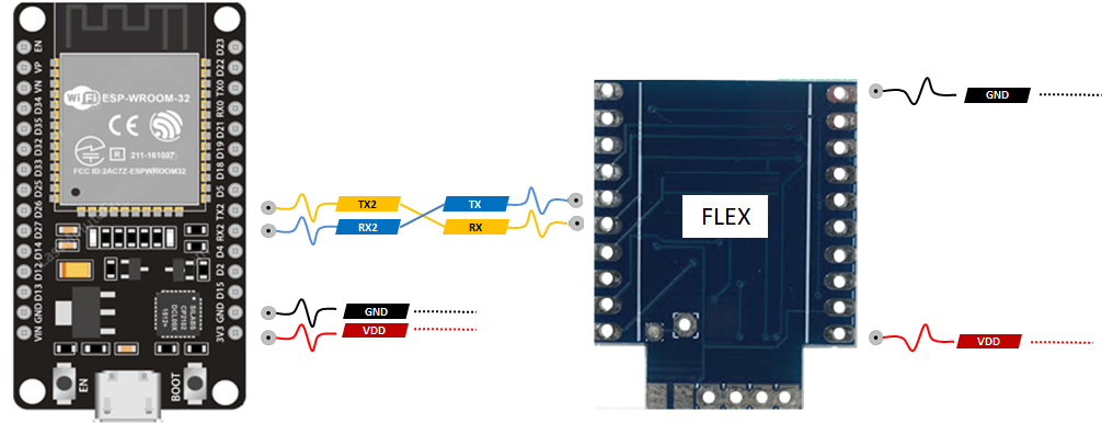
- You can power the Flex Module from the 3V3 pin on the ESP32 Development Board
- The Flex RF Module and the ESP32 Development board need to share the same Ground so connect GND on the ESP32 to pin 10 on the Flex module
- Connect the TX2 on the ESP32 to Flex RX pin (pin 16)
- Connect the RX2 on the ESP32 to Flex TX pin (pin 15)
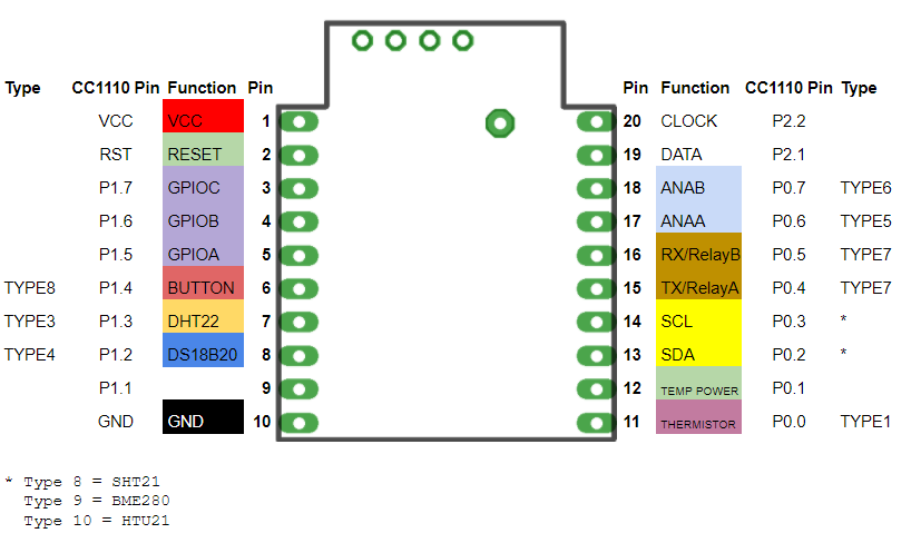
For reference here is the Flex Module pin assignment:
Step 2 - Configure the Flex Module
The Flex module comes shipped as Type 1 (sensor mode). You need to configure the Flex Module for Type 2 (Gateway Mode). Refer these instruction for how to configure the Type and here for an overview of JemRF sensor configuration. Recycle the power on the JemRF module.
Step 3 - Configure the privateeyepi sketch to enable RF communications
In the install tutorial we showed you how to setup up the development environment and you downloaded the JemRF RFLIB library. Now open up the privateeyepi sketch from the examples folder (File->Examples->rflib-master->privateeyepi).
rflib-master example folder then you may not have shut down the Arduino IDE and started it up again.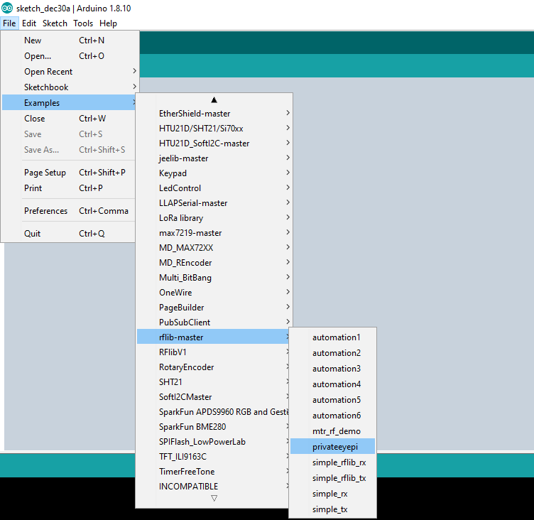
Now save a copy of the example sketch by selecting File->Save As from the main menu and giving it a new name. This will create a new folder in your Arduino directory with the name you gave to it, as well as an .ino file in the new directory.
Near the top of the sketch you will see the following code:
const char* pep_token = ""; //Enter your PrivateEyePi token between quotes
const char* ssid      = ""; //Enter your WIFI router SSID between quotes
const char* password  = ""; //Enter your WIFI password SSID between quotes
Make the following changes:
- Enter your PrivateEyePi token in between the quotes after
pep_token =.
- Enter your WIFI SSID name in between the quotes after
ssid =. The SSID is the name your WIFI router advertises. - Enter your WIFI password in between the quotes
password =. - Edit
~\Adruino\Libraries\rflib-master\pep.hand look for//#define RFnear the top of the file.
//#define RF
- Remove the
//and save the file.
Step 4 - Load the privateeyepi sketch onto the ESP32 Development Board
Click the right arrow button near the top left of the Arduino IDE.
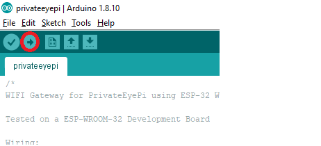
The sketch will compile and you will a green progress bar as it is loaded onto the ESP32 Development Board. Once the upload is complete you will see Done uploading. in the status bar.
Step 5 - Test the JemRF sensors
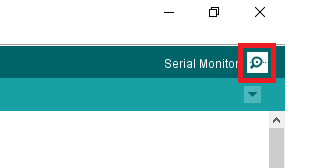
Click the serial monitor on the top right of the Arduino IDE and observe the messages on the screen.
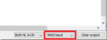
- Set the baud rate to
9600using the drop down box on the bottom right of the monitor window:
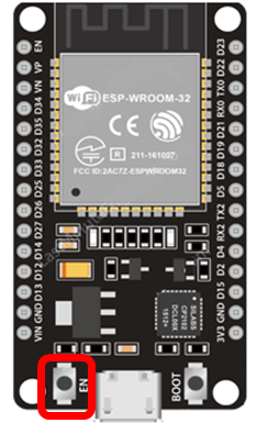
- Push the
ENbutton the ESP32 Development Board to reset the device.
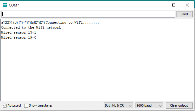
- Monitor the progress as it logs into your WIFI router and configures the switches you configured in Step 2. You should see something like this:
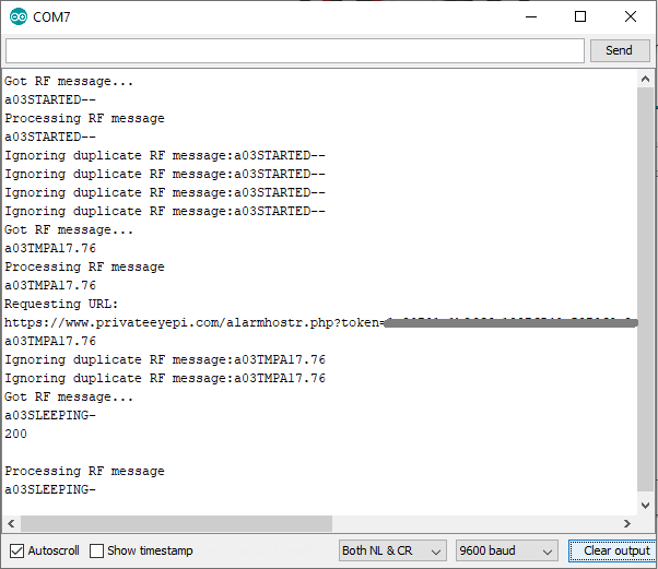
- Power up a JemRF sensor or wait for some sensor activity to occur. Below is the serial monitor data from a temperature sensor that was powered up and transmitted a temperature reading.
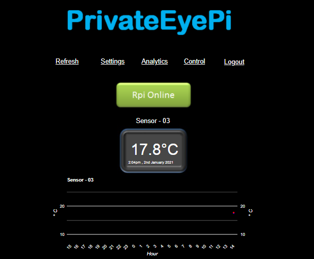
- Open up your PrivateEyePi dashboard and verify the sensor data is being displayed