Connecting an RF device to an MCU
We have a number of different board layouts but each board has a standard edge board connector that can be used to connect a device directly to an MCU (like Raspberry Pi or Arduino). The main reason for doing this is to configure the 16 character password (see sensor encryption). See below diagram for connecting a device to an MCU.
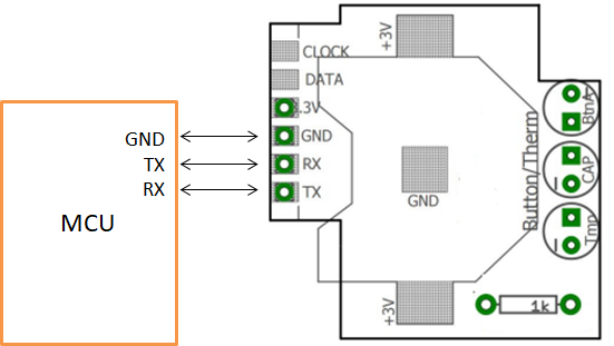
Pinouts
| Flex Pin | Sensor node* | MCU Pin | Raspberry Pi Pin |
|---|---|---|---|
| 1 | 3V3 | 3V3 | 1 |
| 10 | GND | GND | 6 |
| 15 | Tx | Rx | 10 |
| 16 | Rx | Tx | 8 |
Serial Port Settings
The serial port is configured as follows:
Baud : 9600
Data : 8
Parity : None
Stop : 1
Hardware & Firmware
There is common firmware (software that is loaded onto the chip) across all our RF modules. This means you don’t need to load different firmware when you want to re-configure a RF module to do something else. The RF modules are highly configurable. There are however hardware differences (i.e. physical board differences) between some of the sensors that are described in the product pages of each sensor. The Flex modules provides the greatest flexibility because it has 20 pins that expose all of the functionality available on our sensors.
Firmware versions
As we develop more sensors we release new firmware versions for our sensors. You can check the version of a firmware using the VERSION command. The Message Reference Section of this documentation contains details on what functionality is available on each version.